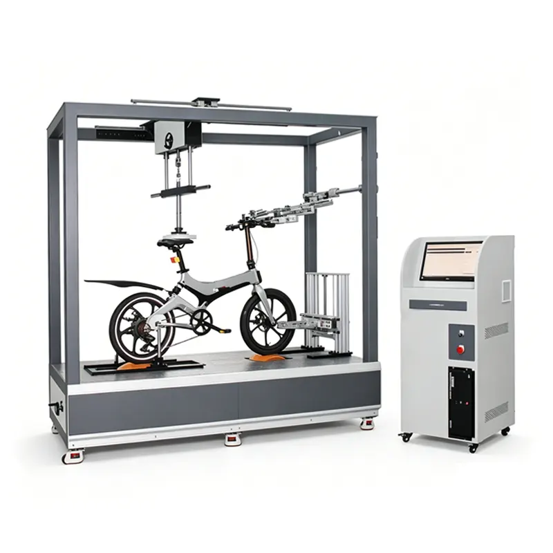
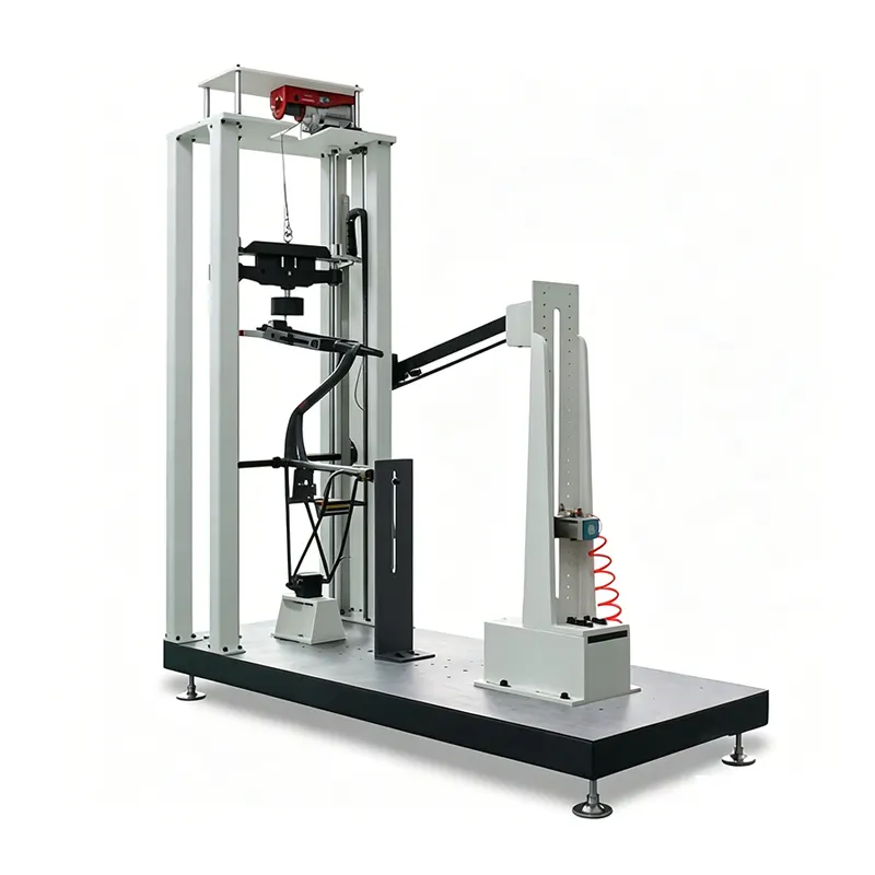
Derui chamber


 Message
E-BIKE DRIVE SYSTEMS · PEDAL INPUT & ASSISTANCE ANALYSIS
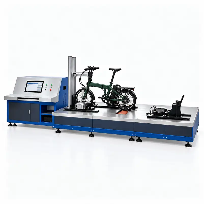
Evaluate how an e-bike responds to a defined pedal input across controlled cadence and loading conditions. Derui’s bicycle power ratio tester provides a project route for comparing pedal input, wheel-side output and assistance behaviour, with the fixture and measurement scope selected for your bicycle and test programme.
Make the ratio meaningful before measuring it
Tell us where power must be measured, how the bicycle will be driven and what decision the result must support. Crank input, motor contribution, electrical input and roller output are different quantities. A useful proposal defines them rather than simply promising a “power ratio” result.
- Control the input: define cadence, torque and assist settings.
- Define the output: specify the measurement boundary and load conditions.
- Keep comparable records: retain setup, channels, calculations and operating state.
Designed Around E-Bike Engineering Decisions
Compare assistance behaviour
Review the response to repeatable cadence and input torque across specified assist settings, speeds and loads. Separate controller behaviour from a change in test setup.
Check a complete drive configuration
Compare motors, firmware or drivetrain combinations on an agreed bicycle configuration. Record battery state, gear selection and tyre conditions alongside the result.
Investigate unexpected performance
Examine a suspected low-output or inconsistent-assistance issue under controlled conditions before changing hardware or software.
This is an industrial test-equipment page, not a rider fitness power meter. The purchasing decision concerns fixture fit, controllable operation and the quality of the measurements available for the engineering task.
Turn a Test Run into a Useful Engineering Comparison
A useful dataset connects each result to the bicycle setup and operating condition. Define the required output in the enquiry so the proposal includes the right channels and calculations.
- Assistance comparisons: compare specified assist settings at the same cadence, input and load points.
- Input/output curves: review the measured relationship over an agreed speed or loading sequence, with the measurement boundary identified.
- Repeatability records: compare repeated runs and document battery state, gear, tyre pressure, temperature conditions and interruptions.
Request a representative report and raw-data example. Required electrical, thermal or additional torque measurements should be listed explicitly; they are not implied by the appearance of a test bench.
Pedal Input, Wheel Output and Motor Contribution
Mechanical power at a rotating shaft is torque multiplied by angular speed: P = T × ω. For torque in N·m and rotational speed in rpm, P(W) = 2π × n × T / 60. Torque and speed must describe the same location and time interval.
A loaded roller receives power after drivetrain and tyre/roller losses. Its measured output is not automatically the motor’s shaft output. Likewise, battery voltage and current describe electrical input, not mechanical output. Confirm the sensor locations, synchronization and any correction or loss model before interpreting a ratio.
| Quantity | What it describes | What must be defined |
|---|---|---|
| Pedal/crank input | Mechanical input supplied at the specified crank-side boundary. | Drive coupling, torque/speed measurement and cadence/load control. |
| Wheel/roller output | Power reaching the defined output interface under load. | Tyre contact or hub coupling, transmission losses and measurement point. |
| Motor contribution / assistance ratio | The contribution or ratio defined by the selected procedure. | Calculation boundary, treatment of losses and valid input range. Near-zero pedal input can make a ratio unstable or undefined. |
| Electrical input | Energy supplied to the drive system at the agreed electrical connection. | Additional power measurement channels, isolation and synchronized recording if required. |
Ask to review a representative dataset and the calculation definition before accepting the software scope. A formula displayed on a screen does not by itself establish measurement accuracy.
Configure the Bench for Your Bicycle and Test Programme
The configuration below is a quotation checklist, not a substitute for model-specific ratings. Confirm the required operating points together: peak torque, continuous power, speed and duration are not independent capacity claims.
| Configuration item | Your requirement | Confirm in the proposal |
|---|---|---|
| Bicycle interfaces | Wheelbase, tyre sizes, crank, axle, frame access and motor layout. | Restraints, adjustment envelope and included adapters; do not assume every mid-drive and hub-motor layout fits. |
| Crank input drive | Cadence, input torque, rotation direction and operating sequence. | Coupling alignment, usable range, control mode and protection. |
| Output loading | Speed, torque, power, duty and low-speed operating points. | Absorber/drive arrangement, continuous versus short-duration operation and cooling. |
| Measurement quality | Required uncertainty or accuracy at the operating points of interest. | Sensor range, calibration conditions, combined measurement performance and verification evidence. |
| Signals and reports | Input/output torque and speed, assist setting, electrical or temperature channels if needed. | Included channels, synchronization, sampling/recording settings and export formats. |
| Utilities and installation | Available electrical supply, space, access and operating environment. | Footprint, services, guarding and installation responsibilities. |
Force, torque or power accuracy should not be inferred from display resolution. Request the basis of an accuracy statement—such as percent of reading or full scale—and verify performance where your test actually runs.
A Repeatable Power Ratio Test Workflow
Align the bicycle
Fit restraints and crank coupling, align the loaded wheel and record tyre pressure, gear, bicycle configuration and assist settings.
Set the operating matrix
Specify cadence, input torque, load/speed points, ramps and dwell. Establish battery conditioning and cooling conditions.
Run and synchronize
Operate the agreed programme and record the supplied channels. Retain stabilization, interruptions and abnormal events.
Compare valid results
Apply the agreed calculation to comparable intervals. Review raw channels and setup conditions alongside the reported ratio.
For acceptance, choose representative low-speed/high-torque and sustained-load points as applicable. Agree on repeat runs, signal checks, protection functions and the output records supplied with the system.
Assistance Testing Is Not Complete E-Bike Certification
An EPAC assessment may include drive-assistance behaviour, but the applicable standard edition, clause and market must be identified first. Request the specific test function and its required evidence; do not treat “EN 15194” as a single software button that certifies a bicycle.
Assisted-speed cutoff, start/stop behaviour, electrical safety, EMC, braking and structural fatigue are different tasks. They are not all established by measuring a power ratio. If a cutoff test or electrical measurement is required, define its fixture, channels, procedure and acceptance separately.
Choose this bench when the central question is input/output power and assistance behaviour. Choose an electric bicycle comprehensive test configuration when you need a separately scoped whole-vehicle mechanical programme. For running durability, review the simulated cycling test bench.
What to Send for a Power Ratio Tester Quote
- Bicycle and drive layout: photographs, drawings, wheelbase, tyres, crank/axle details and motor position.
- Operating matrix: required cadence, input torque, output load/speed, duration and assist settings.
- Measurement definition: ratio or efficiency definition, sensor boundaries and required verification.
- Channels and data: electrical/thermal measurements if required, timestamps, raw data and report format.
- Purchase conditions: representative samples, acceptance points, site utilities, training and schedule.
A useful enquiry starting point
“We need to compare [drive systems/assist settings] on [bicycle]. Required operating points are [cadence, input and output conditions]. Our ratio definition and measurement boundaries are [details]. Please review fixture compatibility, measurement capability and an acceptance demonstration.”
Power Ratio Tester Buying Questions
Is assistance ratio the same as drivetrain efficiency?
No. An assistance ratio describes a defined relationship involving human and motor contribution. Drivetrain efficiency compares output and input across a specified transmission boundary. Define both the quantities and loss treatment before comparing results.
Can a rear roller measure motor power directly?
It measures at the roller boundary. Inferring motor contribution requires the agreed input measurements and treatment of transmission/contact losses. It should not simply be labelled direct motor-shaft power.
Will every mid-drive or hub-motor e-bike fit?
Compatibility depends on geometry, crank coupling, wheel interface, restraint and access. Provide the intended bicycle families and confirm adapters individually.
Can a claimed maximum rating be used continuously?
Not without checking the rating basis, cooling and duty. Specify the full torque-speed-duration operating point and ask the proposal to identify continuous and temporary limits.
What must be included in the acceptance run?
Check installation, channel verification, operating points, repeatability, calculations, records and protection functions using the agreed bicycle and setup.