Derui chamber


 Message
BICYCLE COMPONENT TESTING · SEAT-POST STRUCTURAL EVALUATION
Compare seat-post designs and investigate structural durability under a defined repeated-loading programme. Derui’s bicycle seat post fatigue testing machine is intended for component test projects where the support fixture, insertion depth and load application point must match the part being evaluated.
Start with the post, clamp and loading point
Send the post drawing, minimum insertion condition and test procedure. Ask Derui to review the support fixture, saddle or dummy adapter, operating requirements and records before selecting the machine configuration.
- Match the specimen: round or shaped post, rail/head interfaces and exposed length.
- Define the load: force direction, application point, waveform and test sequence.
- Document the outcome: test history, interruptions, inspections and acceptance criteria.
Seat-Post Testing for Component Development and Quality
Compare design revisions
Evaluate a tube, head or clamp change under the same mounting and loading conditions. Keep geometry and specimen preparation consistent between revisions.
Review the specified assembly
Match the saddle-rail interface, post and support condition required by the programme rather than testing an unrelated tube in a convenient grip.
Examine a failure concern
Use an agreed static or repeated-loading procedure to investigate loosening, deformation or structural damage and retain the setup evidence.
A seat-post is the component fitted into the frame’s seat tube. A standalone post fixture is not automatically a frame seat-tube test, and a structural loading test is not the same as repeatedly operating a dropper mechanism.
Choose the Test Task Before Choosing the Fixture
A seat-post tube, its head assembly and the saddle-clamp interface are not the same test object. Define the assembly that must be assessed before comparing equipment quotations. The tasks below are scope-review items, not a list of functions included in every machine.
| Test objective | Assembly to define | Evidence to request |
|---|---|---|
| Seat-post structural fatigue | Post, support sleeve or grip, exposed length and prescribed loading adapter. | Fixture drawing, force direction, operating programme and post-test inspection record. |
| Saddle / clamp assembly evaluation | Saddle or rail interface, post head, fasteners and specified load contact. | Correct adapter, assembly settings and assessment of the interfaces included in the test. |
| Static strength or security task | Applicable assembly, restraint and prescribed holding sequence. | Separate confirmation of static control, force range and required observations. |
| Dropper actuation endurance | Extension/retraction mechanism, remote actuation and operating state. | A separately defined functional test setup; not established by structural fatigue capability. |
Why Insertion Length and Loading Geometry Matter
The exposed length, support angle, clamp contact and force application point affect the bending moment experienced by the post. Two tests using the same force can load the specimen differently if the fixture or adapter position changes.
Support the post without creating the wrong failure
Specify insertion depth, gripping length, tube profile and the permitted clamping arrangement. A round-post sleeve should not be assumed to fit an aero profile. For carbon-composite parts, review contact shape, surface protection and clamp torque. Excessive or uneven gripping can damage the specimen and distort the result.
Define the upper interface
Identify whether the programme uses the actual saddle, a compatible rail assembly or a prescribed dummy adapter. Record rail dimensions, fore/aft position and loading offset. Head and saddle-clamp behaviour cannot be inferred from a test that bypasses those interfaces.
Keep a setup drawing or photograph with insertion marks, support angle, adapter position and fastener settings. This helps distinguish a product difference from a mounting difference.
Seat Post Tester Configuration Checklist
Confirm numerical ratings for the proposed model and installed fixture. A load sensor’s capacity is not the force prescribed by a standard, and a static maximum does not establish dynamic fatigue capability at every frequency.
| Configuration item | Requirement to define | Confirm in the quotation |
|---|---|---|
| Specimen and grip | Diameter/profile, length, insertion and support angle. | Grip/sleeve geometry, adjustment and included specimen-specific adapters. |
| Load interface | Saddle, rails or dummy adapter; load point and direction. | Adapter drawing, clearances, alignment and restraint. |
| Force programme | Static/repeated load, waveform, frequency, cycles and sequence. | Usable force-motion-frequency envelope under the proposed setup. |
| Measurement | Force and any displacement channels; required verification. | Sensor range, accuracy basis, recording settings and calibration/verification evidence. |
| Control and stopping | Controlled variable, limits, inspections and stopping conditions. | Feedback/control functions and explicitly defined stop triggers. |
| Records and utilities | Required reports, available services and installation access. | Output formats, fixture/setup documentation, footprint, utilities and support scope. |
Ask for the configuration sheet to distinguish standard items, additional fixtures and optional measurements. If displacement is required, define whether it is measured at the actuator or directly at the specimen; machine and fixture compliance can affect interpretation.
A Four-Step Seat-Post Test Workflow
Identify the specimen
Record post identity, geometry, assembly condition and the applicable procedure. Inspect and document the specimen before mounting.
Set the boundary conditions
Install the grip, insertion depth, upper adapter and load alignment. Record support angle and fastener settings.
Run the programme
Apply the agreed sequence and retain actual measurement channels, cycle count, interruptions and inspection observations.
Assess the defined outcome
Record why the test stopped, completed conditions and inspection findings. Compare with the programme’s acceptance criteria.
Define the inspection schedule and supervision level. A stop caused by force loss or travel change is not guaranteed detection of every crack or delamination. Agree on how damage and loosening are checked during and after the run.
ISO 4210-9 Scope and Dropper-Post Boundaries
ISO 4210-9:2023 specifies saddle and seat-post test methods associated with ISO 4210-2. Identify the relevant test, edition, bicycle category and specimen assembly before defining equipment capability. Static security/strength and fatigue tasks should not be treated as interchangeable.
Use the controlled procedure to establish forces, geometry, cycle requirements and acceptance—not the product title or a generic brochure. A seat-post result does not certify a complete bicycle, and an EPAC project may require additional assessments beyond this component test.
Structural fatigue is not dropper actuation life
A dropper post can be evaluated for a specified structural loading task if its mounting and operating state are suitable. Repeated extension/retraction, remote actuation, lockout behaviour, friction or seal leakage are separate functional tests. They require a defined actuation system, load state and measurements; they are not included simply because a dropper fits the grip.
For frame-level loading, review the bicycle frame vertical fatigue tester. For a complete-bicycle mechanical programme, review the electric bicycle comprehensive test configuration.
Agree on Equipment Acceptance Before Purchase
Use a representative component and the proposed installed fixture for the acceptance trial. A demonstration with a different grip or a rigid dummy does not, by itself, establish suitability for your production post.
Check the interfaces
Review insertion marks, grip contact, adapter clearance, alignment and practical access for mounting and inspection.
Check the operating task
Agree on a trial programme and evidence of measured loading under the proposed conditions. Review stopping functions and protection arrangements.
Check the delivered evidence
Specify setup instructions, measurement verification documents, example records, operating guidance and the training scope.
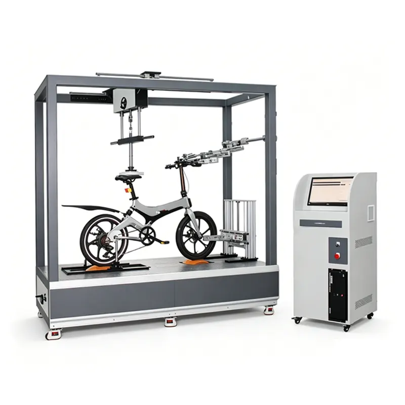
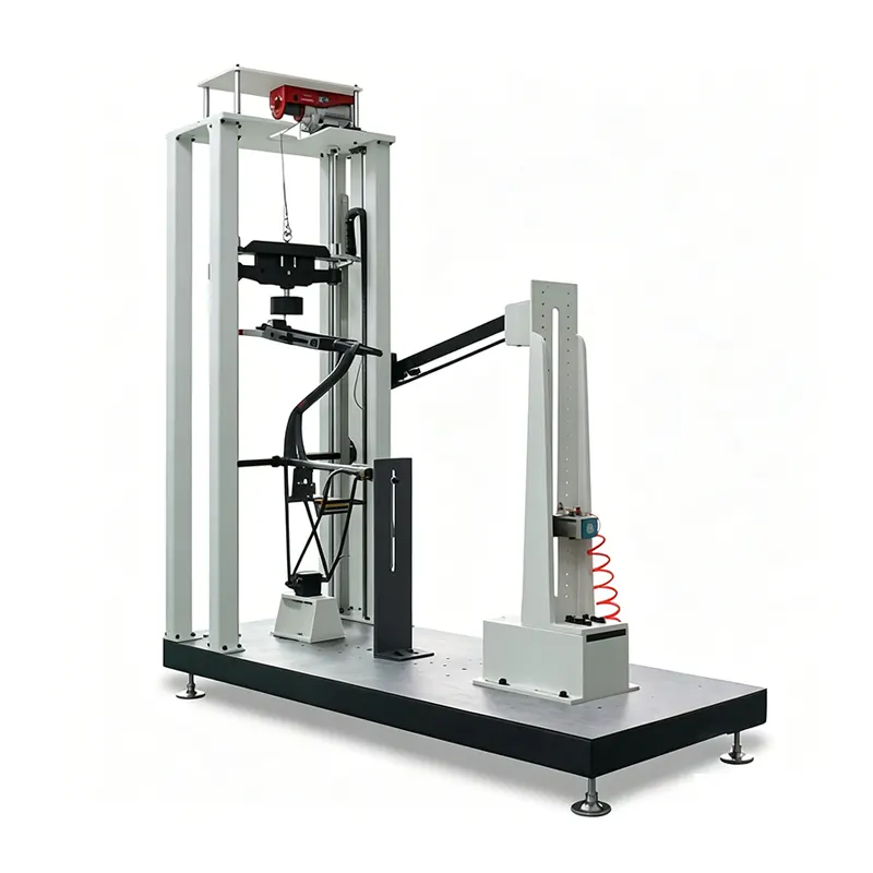
Confirm what is included, optional or excluded in the written proposal. Guarding and access protection must be reviewed for the actual installation; the open appearance concept images do not define the machine’s safety arrangement.
What to Send for a Seat Post Tester Quote
- Post and assembly drawings: profile, length, minimum insertion, head/rail interface and material.
- Fixture conditions: support angle, clamp details, torque and loading adapter or saddle arrangement.
- Test programme: procedure/edition, bicycle category, required force history, frequency and cycles.
- Records: channels, inspection rules, verification documents and output format.
- Acceptance and site: representative samples, trial tasks, utilities, installation and training needs.
Request a configuration review for your component
Send the drawing and test procedure, and identify any fixture or reporting requirements already defined by your laboratory. Derui can review the proposed scope with you before an equipment configuration is agreed.
Include changeover requirements if you test multiple post profiles. Confirm the grip and adapter scope for each family rather than assuming a universal fixture.
Seat Post Tester Buying Questions
Is this a seat tube or a seat-post test?
This page concerns the seat-post component and its specified assembly interfaces. Testing the frame’s seat tube requires the relevant frame fixture and method.
Can it test carbon and alloy posts?
Suitability depends on geometry, gripping, loading and inspection requirements, not material alone. Supply drawings and samples so contact conditions and adapters can be reviewed.
Can one grip cover different post diameters and aero profiles?
Not automatically. Define each profile, gripping length and insertion condition. Confirm the required sleeves or dedicated adapters, adjustment range and changeover procedure in the quotation.
Does a maximum force rating prove fatigue capability?
No. Dynamic capability must be considered with motion, frequency, specimen stiffness and fixture. A static maximum or sensor capacity is not the full fatigue operating envelope.
Are force curves and data export included?
Confirm the installed sensors, recording functions and output formats for the quoted controller. Ask for an example record; a touchscreen in an appearance image does not establish those functions.
Can it automatically find every structural failure?
No such claim should be assumed. Define measured signals, stop thresholds and inspection methods. Some damage requires visual or other examination beyond controller monitoring.
How often should measurements be verified?
Use the laboratory’s quality procedure, instrument requirements, usage and risk assessment. Agree on checks after relevant maintenance, overloads or fixture changes; do not assume a universal interval.