Derui chamber


 Message
BICYCLE FRAME TEST EQUIPMENT · VERTICAL FORCE FATIGUE
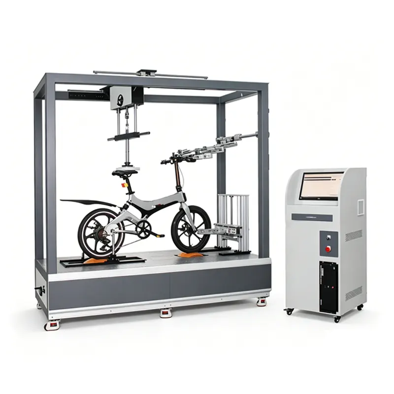
Evaluate bicycle frames under repeated vertical loading with a test setup matched to the frame, fixture interfaces and selected method. Derui’s bicycle frame vertical fatigue testing machine is intended for frame development and laboratory durability programmes where the loading point, force history and test records need to be defined clearly.
Send the frame drawing, seatpost or loading-adapter dimensions, axle interfaces and test procedure. Derui can review the vertical loading arrangement, fixture fit and required control and measurement scope before quotation.
Vertical Loading for Bicycle Frame Fatigue Evaluation
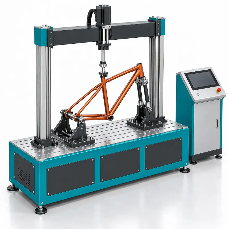
The test applies repeated force through the loading assembly specified by the procedure while the frame is supported at defined interfaces. It allows a laboratory to evaluate a frame’s response to that loading programme and record the outcome against the agreed inspection and acceptance criteria.
The loading point, its position relative to the frame and the permitted movement at the supports all affect the test. A frame held in an unsuitable fixture can experience a different load path, even when the controller displays the intended force.
Frame development
Compare design revisions under the same specimen preparation, mounting and vertical loading conditions.
Laboratory validation
Run the defined procedure and retain specimen, setup and test records for engineering review.
Quality investigation
Examine a frame or manufacturing change using a repeatable loading programme and inspection plan.
This page concerns vertical-force frame fatigue. Horizontal-force fatigue, pedalling-force fatigue, impact tests and complete-bicycle running tests require their own fixtures and loading arrangements. They should not be assumed to be included in this configuration.
Bicycle Frame Vertical Fatigue Tester Configuration
Specify the operating conditions needed for your frame and method. The items below define the equipment configuration to review; numerical ratings and included functions must be confirmed in the model-specific proposal.
| Configuration item | Requirement to define | What to confirm |
|---|---|---|
| Vertical loading | Force application point, direction and required force history. | Loading arrangement, adapter geometry and operating limits for the proposed setup. |
| Force measurement | Required measurement range, accuracy and verification conditions. | Load sensor, verification documents and usable dynamic performance. Sensor capacity is not the prescribed test force. |
| Frequency and waveform | Method-defined frequency, waveform and loading sequence. | Achievable conditions with the specimen and fixtures installed. |
| Actuator travel | Required motion, setup adjustment and clearances. | Usable stroke under load. Total actuator travel is not the required fatigue amplitude. |
| Control and records | Controlled variable, signal channels and recording/export needs. | Control functions, cycle counting, output formats and stopping conditions. |
| Fixture adjustment | Frame geometries, axle interfaces and loading-adapter dimensions. | Included fixtures, adjustment range and sample-specific adapters. |
| Site requirements | Available utilities, access and installation conditions. | Footprint, utilities, guarding and installation responsibilities. |
Compare force, motion and frequency together for the proposed test. Ask for a configuration sheet that separates standard equipment, specimen-specific tooling and optional measurements.
Frame Fixtures and the Vertical Load Path
Match the fixture to the frame interfaces
Provide axle/dropout details, frame dimensions, head-tube and fork or substitute-fork interfaces, and seat-tube/seatpost information. Identify which components are installed during the test and which are replaced by test adapters. The fixture arrangement must follow the procedure rather than simply holding the frame wherever it is convenient.
Define where the force enters the frame
Specify the loading-adapter geometry, seatpost insertion or extension condition and force application point. A change in adapter offset or support position can change the forces and moments experienced by the frame. Agree on the loading alignment and a setup check before testing.
Plan changeovers between frame families
A road frame and a hardtail mountain-bike frame may require different adapters or adjustment positions. Material alone—carbon composite, aluminium, steel or titanium—does not establish compatibility. Share the smallest and largest geometries you want to test, including unusual axle interfaces or frame shapes.
Suspension frames, step-through frames and cargo applications need individual review of the setup and method. Do not assume the same fixture and bicycle-category requirements apply to every design.
Force Control, Inspection and Test Records
Force feedback is used to control the prescribed loading programme. Agree on how the laboratory will verify the installed force measurement, check the actual waveform and monitor the test. A controller setting alone does not show that the specimen is receiving the intended loading history.
- Before the run: record frame identity, fixture positions, loading-adapter dimensions, sensor information and the selected programme.
- During the run: retain the agreed force/motion records, cycle count, interruptions, alarms and inspection observations.
- At the end: record why the run stopped, completed cycles and inspection findings against the method’s acceptance criteria.
Confirm which channels, sampling/recording settings and export formats are supplied. Review a representative output before finalising the software scope.
Define protection and stopping conditions
Agree on overload and travel limits, loss-of-force response, emergency stop and guarding appropriate to the test area. If an automatic stop is triggered by force deviation or another signal, identify the trigger and threshold. That function should not be described as automatic detection of every crack or delamination.
ISO 4210-6 Test Scope and Method Selection
ISO 4210-6:2023 specifies bicycle frame and fork test methods associated with ISO 4210-2:2023. Vertical-force fatigue is distinct from the horizontal-force and pedalling-force frame tests. Confirm the applicable edition, bicycle category and clauses before defining the programme.
The test method, rather than the machine name, determines the specimen preparation, loading conditions, cycle requirement and acceptance criteria. A vertical fatigue result does not by itself demonstrate that a bicycle has passed every part of ISO 4210.
For an EPAC project, identify the mechanical frame test required within your EN 15194 assessment. This machine should not be treated as evidence that electrical safety, EMC or the complete bicycle assessment has been completed. Special-purpose bicycles and customer-specific programmes require their own scope review.
What to Send for a Frame Fatigue Tester Quote
| Your input | Why it matters |
|---|---|
| Frame drawing and sample photographs | Define overall geometry, mounting interfaces and access around the specimen. |
| Seatpost/loading adapter and support details | Establish the load application point, offsets and boundary conditions. |
| Procedure, edition and bicycle category | Set the relevant test conditions and inspection/acceptance requirements. |
| Required force history, frequency and cycles | Check compatible operating conditions for the frame and proposed fixture. |
| Data, verification and acceptance records | Define channels, output formats and the evidence needed for equipment acceptance. |
| Installation country, utilities and schedule | Confirm site preparation, delivery and support responsibilities. |
Ask the proposal to identify included fixtures, adapters, sensors, control software, documentation and any optional functions. Agree on a representative factory acceptance trial, installation/training scope, warranty and support terms before purchase.
“We need vertical-force fatigue testing for [frame type]. Our drawings and interfaces are [details]. We will use [procedure/edition] with [required loading programme]. Please review fixture fit, operating capability and the records included in the proposal.”
If the specification is still being prepared, use the test machine RFQ checklist to organise the available information and open questions.
Questions Before Selecting a Vertical Frame Fatigue Tester
Does the sensor capacity determine the test force?
No. The sensor rating identifies its capacity. The test force comes from the selected method or engineering programme, and the machine must achieve it under the required dynamic conditions.
Can this configuration also perform horizontal or pedalling-force tests?
Those are separate loading arrangements. Request them explicitly if needed; confirm whether additional actuators, fixtures or another machine are required.
Can the same equipment accept different frame materials and sizes?
Compatibility depends on geometry, interfaces, loading and available adjustment, not only the material name. Provide drawings for each intended frame family and confirm the required adapters.
How long will a fatigue test take?
Run time depends on the specified cycles and frequency, plus ramps, inspections, pauses and interruptions. Confirm the programme before estimating throughput. A completed run should not be converted into years of road use without a validated correlation.
What should be demonstrated before shipment?
Agree on specimen installation, loading alignment, measurement verification, representative operation, stopping functions and the records supplied. Use the agreed acceptance checklist to compare the delivered system with the quotation.