Derui chamber


 Message
FROM VEHICLE INSTALLATION TO USEFUL TEST EVIDENCE
Electric Motorcycle Testing Starts with a Repeatable Setup
A change in tyre condition, restraint or cooling can make two runs difficult to compare—even when the motorcycle has not changed. Specify the installed condition as carefully as the load programme.
Discuss Derui’s electric motorcycle test bench for evaluating an assembled vehicle through its driven tyre and a dynamometer roller arrangement. Start with the question your team needs to answer, then review the vehicle fixture, loading system and measurement channels. This gives engineering and procurement teams a clearer basis for comparing equipment proposals.
Compare vehicle changes
Plan controlled comparisons of vehicle variants or settings, with the installation, preparation and operating conditions recorded.
Define the duty
Specify the speed, load, duration and cooling needed to investigate behaviour during the agreed operating programme.
Separate screening from endurance
A short release check and a development endurance run need different sequences, handling and acceptance evidence.
Fit the Motorcycle Before Specifying the Test
Provide wheelbase, vehicle dimensions and mass, tyre diameter and width, ground clearance, suspension movement and driven-wheel layout. Identify whether the project uses a hub motor or a transmission-driven rear wheel, and whether any front-wheel or dual-wheel drive must be accommodated.
Keep the vehicle and test lane aligned
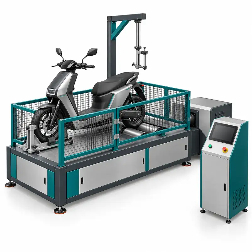
For the illustrated rear-wheel arrangement, the motorcycle’s front and rear wheel centre planes follow the same longitudinal line as the front locator, rear roller station and loading route. A vehicle positioned diagonally across the bed changes the contact and restraint conditions; it is not a substitute for suitable fixtures.
Review wheel location, permitted restraint points, suspension position and clearances with a representative vehicle. Define tyre pressure and condition, tie-down settings and any preparation between runs. A rear-wheel test layout is not automatically suitable for a different driven-wheel arrangement.
The reference design includes an overhead structure. Its contact point, operating purpose and effect on the vehicle must be defined in the technical scope. Its appearance alone does not establish rider-mass simulation, a specified load capacity or automated riding.
Choose the Working Conditions, Not Just a Maximum Rating
Request the speed and load combination needed throughout your programme. Include duration at each point and the required acceleration or deceleration. A peak power figure does not establish continuous capability, and separate maximum ratings should not be assumed to occur together.
- Operating points: vehicle speed, tractive force or torque, duration and permitted variation.
- Transitions: ramps or speed traces, tracking requirements and the method of operating throttle and brakes.
- Thermal conditions: cooling airflow, ambient conditions, vehicle limits and any required temperature channels.
- Load model: resistance or inertia inputs and how they will be verified, if road-load reproduction is required.
Confirm whether the task requires absorbing vehicle output, actively driving the roller, or both. These require different capabilities. Vehicle energy recovery into its battery is also different from the dynamometer returning electrical energy to the facility supply.
Specify any steady-load, transient, deceleration or endurance task explicitly. It should become part of the agreed configuration and acceptance demonstration—not an assumption based on the words “AC”, “eddy current” or “regenerative”.
Know What Each Result Represents
Define the measurement point before comparing a power or efficiency figure. The tyre, transmission and test bed can affect interpretation; the result must identify the boundary actually measured.
| Required result | Specify in the proposal | Important distinction |
|---|---|---|
| Mechanical output | Force or torque location, speed reference, calculation and any correction method. | Roller output, wheel output and motor-shaft output are not interchangeable. |
| Electrical energy | Voltage/current measurement point, range, sign convention and integration interval. | A mechanical power curve alone does not measure battery consumption. |
| Efficiency or recovery | Mechanical and electrical records synchronized over the same operating interval. | Overall energy flows do not automatically isolate motor, inverter and battery losses. |
| Distance or range | Speed/distance source, vehicle preparation, load model, conditions and endpoint. | Roller distance under an arbitrary programme is not a guaranteed road range. |
| Vehicle behaviour | Available temperatures or vehicle signals, interfaces, timing and recording. | A CAN connector does not establish access to every proprietary signal. |
For each channel, agree on range, accuracy definition, sampling or update rate, synchronization and verification. A sensor’s individual specification should not be presented as the accuracy of the complete installed measurement system.
Make the Supplied Configuration Easy to Compare
Request a model-specific specification against your vehicle and programme. The following items should be identified as included, optional or outside the proposed scope, rather than grouped into a single list of assumed functions.
| Scope item | What to confirm |
|---|---|
| Test bed and vehicle fixture | Installed dimensions, wheel/roller arrangement, locating adjustment, restraints, access and handling. |
| Loading equipment | Actual absorber or drive architecture, combined operating envelope, cooling and duration limits. |
| Upper structure | Purpose, contact interface, working range and control, if included in the approved arrangement. |
| Instrumentation | Installed mechanical, electrical and temperature channels, vehicle interface scope and calibration evidence. |
| Operation and output | Manual or automated sequence, driver display, programme tracking, stored records and actual export formats. |
| Site and delivery | Utilities, floor/anchoring, cooling, protection, manuals, training, service responsibilities and acceptance records. |
Battery simulators, additional electrical instruments, vehicle communication and automated operating systems require explicit review. An equipment image does not prove that these items are supplied.
Agree on Acceptance with a Representative Motorcycle
Before purchase, identify the sample vehicle, working conditions and records that will demonstrate the proposed equipment. A useful acceptance run connects the physical installation to the results your team needs.
Identify the test
Record the vehicle revision, battery condition, programme, target results and acceptance criteria.
Verify the setup
Check alignment, tyre contact, fixtures, clearances and the approved operating arrangement.
Run the agreed duty
Demonstrate the required load/speed conditions, available channels and defined stop responses.
Accept the evidence
Review recorded results, interruptions, measurement checks and the final delivery scope.
Keep a sample record showing the requested and achieved conditions, timestamps, channels, units and stop reasons. Agree on how an interrupted run is retained and restarted; do not present it as a completed pass.
Guarding is part of the engineering scope
Review roller nip points, tyre or restraint failure, overspeed, stored energy and powered-battery hazards. Confirm guarding, access control and stopping behaviour for the actual installation. Mesh fencing and an emergency-stop symbol in a concept image do not establish a validated safety system or permission for unattended operation.
Electric Motorcycle Test Bench Buying Questions
Does a chassis test bench measure motor-shaft power?
Not directly from tyre-to-roller measurements alone. Identify the measured mechanical boundary and any calculation or loss correction. Direct motor-shaft evaluation is a different connection and instrumentation task.
Can it evaluate regenerative braking?
Review the required deceleration, mechanical energy source or inertia behaviour, load/drive control and synchronized electrical measurements. Do not assume this scope from a motor type or the presence of an inverter.
Are WMTC, WLTP or other formal programmes included?
A named cycle is not a blanket equipment certification. Provide the target market, vehicle category and controlled method/version. The roller configuration, load control, vehicle operation, cooling and records need to match the specified task. Included programmes require demonstration.
Can it test different motorcycle sizes or drive layouts?
Send the dimensions, mass, tyres, driven-wheel arrangement and operating requirements for each variant. Suitability depends on the actual fixtures and working envelope, not simply whether a vehicle is called an electric motorcycle.
What determines the equipment price?
Vehicle fit, load/speed/duration requirements, drive architecture, instruments, automation, fixtures, protection and delivery scope all affect the proposal. A drawing and defined test programme make quotations easier to compare.
Is it the same as a battery-pack EOL test bench?
No. This discussion concerns an assembled motorcycle on a roller test arrangement. Battery-pack electrical checks require a separately defined connection, instruments, safety scope and acceptance programme.
Get a Proposal Built Around Your Motorcycle Test
Send vehicle drawings or photographs, dimensions and mass, tyres and drive layout, required speed/load points, duration, measurements and installation conditions. Include any formal method and the evidence you need at acceptance.