Derui chamber


 Message
SCOOTER TEST EQUIPMENT · COMPLETE-VEHICLE ROLLER DURABILITY
Assess how a scooter assembly changes during a defined rolling test—not just whether an isolated component withstands a static load. Derui’s scooter dynamic durability test machine uses a complete-scooter roller arrangement, with specimen restraint and deck loading reviewed around the required laboratory programme.
Build the running test around your scooter
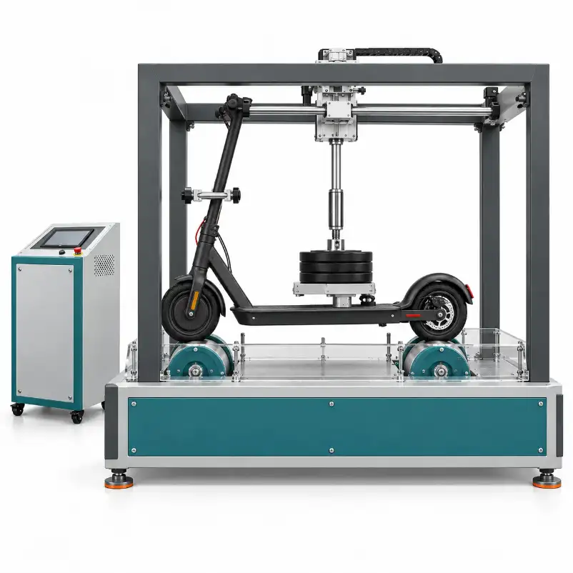
The reference arrangement places the front and rear wheels on separate roller drums, with an upper restraint and a central deck-loading fixture. Use your scooter dimensions and test procedure to confirm fit, loading and the evidence required from the proposed configuration.
- Fit: wheelbase, tyre dimensions, ground clearance and steering position.
- Test conditions: roller surface, speed, deck loading and any specified obstacle input.
- Evidence: run completion, interruptions, inspections and installed measurement channels.
What Complete-Scooter Dynamic Durability Testing Can Assess
A roller-running programme can expose changes in an assembled scooter under prescribed contact, loading and repeated input conditions. Define the observations and acceptance criteria before testing; a machine running for a long time does not by itself establish a useful result.
Compare assembly revisions
Compare deck, stem, folding-joint or suspension revisions using consistent installation and running conditions.
Investigate developing change
Inspect for increasing play, loosening, deformation, wheel damage or other specified changes during the programme.
Reproduce a defined method
Review the required specimen preparation, load application, road-input geometry and records before selecting equipment.
This is an assembly durability task. A wheel-material abrasion test, static deck load, motor endurance run and whole-vehicle range test answer different questions and may require different equipment or measurement functions.
Wheel Contact, Deck Loading and Restraints Must Work Together
Match the wheelbase and contact geometry
Provide the front-to-rear wheel spacing, tyre diameter and width, ground clearance and any relevant suspension movement. Review where each wheel sits on its drum and whether the specimen remains correctly aligned throughout the required motion. Confirm actual adjustment limits rather than assuming every scooter size fits.
Specify where the load reaches the deck
The reference image shows a central loading arrangement. Define the required load application point, contact area and freedom of movement for your procedure. The mass of weight plates alone is not proof of the effective load reaching the specimen if a guide, support or restraint carries part of it.
Review whether the loading fixture can follow the required scooter movement without binding or adding unintended forces. Define the assembly adjustment positions and tyre preparation so repeat runs use the same starting conditions.
Restrain the vehicle without bypassing the test
The fixture must keep the scooter on the rollers while preserving the movement allowed by the method. An upper restraint that unintentionally supports the deck load, locks out suspension movement or changes the stem load path can alter the result. Record its attachment and permitted freedoms.
Retain photographs, specimen identification, tyre condition, loading position, restraint settings and any specified fastener preparation. Do not change the fixture or tighten a joint during a run without recording the intervention and following the procedure.
Define the Roller Programme, Not Just the Test Duration
| Condition | Why it matters | What to agree |
|---|---|---|
| Drum geometry & surface | Wheel contact on a curved drum differs from flat-ground contact. | Required diameter, surface, contact arrangement and usable specimen envelope. |
| Running speed | Roller surface speed is not simply the drum’s rotational speed. | Surface-speed target, verification method and allowed variation under load. |
| Obstacle input, if required | Profile, spacing and front/rear encounter sequence define the repeated input. | Shape, dimensions, attachment, spacing and compatibility with the specified method. |
| Loading & restraint | Load distribution and fixture freedoms influence the assembly response. | Application point, effective load, contact area and restraint conditions. |
| Completion basis | Time, roller distance and obstacle events describe different quantities. | Required endpoint, interruption handling and the meaning of the displayed counter. |
A smooth-roller run does not automatically include an obstacle test. Likewise, a repeating raised feature is a defined laboratory input, not evidence that the machine reproduces every pothole, kerb or road surface. Confirm the actual obstacle configuration separately.
Clarify how the rollers and scooter are driven
Specify whether the rollers drive the wheels or the scooter operates under its own power, and how front/rear drum speeds are coordinated where needed. A powered scooter requires an agreed operating state and safety plan. The image does not establish either drive mode.
A roller endurance setup is not automatically a chassis dynamometer. Power, torque, road-load simulation, battery consumption and range results require their own instrumentation, loading model and validated procedure. Do not treat an unloaded rolling distance as a verified real-world range.
Choose Evidence That Explains the Run
Decide what must be observed during operation and what will be measured before, between or after test intervals. Separate controller counters from independent measurement channels.
- Run history: specified speed, completion basis, elapsed operation and interruption record.
- Assembly inspections: defined locations for cracks, deformation, looseness, play and wheel or tyre damage.
- Optional measurements: force, acceleration, displacement, temperature or electrical channels only where specified and installed.
- Stop criteria: completion, specimen change, loss of contact or another agreed condition; identify how each condition is detected.
- Result traceability: specimen revision, fixture settings, procedure version and permitted interventions.
Automatic crack detection, continuous impact-force logging, vibration spectra and remote monitoring are not implied by a touchscreen. Ask for the proposed hardware, acquisition settings and a representative output file if these are required.
Configuration Points to Confirm Before Purchase
Use a sample-matched technical proposal rather than comparing unverified maximum load or speed claims. The items below define the purchase discussion; rated values must come from the actual offered model.
| Equipment area | Your input | Confirm in the quotation |
|---|---|---|
| Specimen installation | Drawing, wheel dimensions, wheelbase, clearance and adjustment positions. | Supported geometry, positioning, restraints and included adapters. |
| Roller system | Required contact geometry, surface and running programme. | Drum dimensions, drive arrangement, usable speed range and verification. |
| Load application | Load, location, contact area and allowed specimen movement. | Loading fixture, supplied weights or other loading method and effective-load checks. |
| Obstacle arrangement | Required method and obstacle geometry, if applicable. | Included elements, drum attachment and encounter sequence. |
| Control & evidence | Endpoint, stop rules, records and additional measurement needs. | Installed functions, recording/export, restart behaviour and demonstration records. |
| Site & safety | Utilities, space, access, noise and operating requirements. | Supply requirements, guarding, emergency controls, instructions and acceptance scope. |
Confirm whether the package includes sample-specific fixtures, obstacles, verification documents, spare wear parts, installation and training. Environmental exposure or data-system integration requires separate engineering review, not an assumed accessory.
Use the Correct Scooter Category and Test Procedure
EN 14619 addresses kick scooters within its scope. Electric personal-mobility projects may instead involve EN 17128 within its scope or another applicable requirement. The vehicle category, target market, standard edition and exact test method must be established before the rig is configured.
Provide the controlled procedure for specimen preparation, loading, roller geometry, obstacles, speed, endpoint and inspections. The proposed equipment must be checked against that task; a roller test does not establish every requirement of a complete-vehicle standard.
For internal endurance development, document the programme and its rationale. Increasing speed or adding obstacles changes the input: it is not automatically a validated acceleration factor. Laboratory hours or distance cannot be converted directly into years of service without a justified correlation.
A Four-Step Roller Durability Workflow
Select the programme
Identify the assembly revision, procedure, operating state and assessment criteria.
Verify the setup
Check wheel contact, effective loading, restraints and required clearance.
Track the test history
Retain the agreed run records, inspections, stops and interventions.
Inspect the assembly
Compare the defined changes against the procedure and acceptance criteria.
Demonstrate the Configuration With Your Scooter
Before equipment acceptance, use a representative specimen to demonstrate installation, the required running condition and the agreed outputs. Separate equipment acceptance criteria from the scooter’s own pass/fail criteria.
- Fit and movement: demonstrate roller contact, restraint positions, load application and clearance through the required specimen movement.
- Operating condition: verify speed and loading by the agreed method; demonstrate the obstacle arrangement if included.
- Control behaviour: show programme completion, the specified stop inputs, data retention and a deliberate restart procedure.
- Handover: review output files, fixture instructions, verification documents, wear-part information and training.
Address wheel/roller nip points, moving weights, tyre or specimen failure and any powered battery assembly. An open product visualization is not a complete guarding design. Follow the supplied instructions and laboratory risk controls.
If your target is an isolated joint rather than rolling assembly exposure, review the scooter folding mechanism fatigue tester or steering assembly test configuration. These tasks are complementary, not substitutes for the same test.
What to Send for a Scooter Dynamic Durability Tester Quote
- Scooter: drawing, photographs, wheelbase, tyre size, clearance and relevant adjustment positions.
- Test: procedure or standard edition/clause, rolling/obstacle requirement, speed and completion basis.
- Loading: required load, application point, contact area and permitted fixture movement.
- Assessment: inspection criteria, stop rules, measurement channels and records.
- Supply: specimen variants, site utilities, protection, fixture changeover and acceptance trial.
Get a proposal that defines the complete setup
Share the specimen and required programme. Derui can review the roller arrangement, loading, restraints and reporting scope so your team can compare what is actually included.
Scooter Dynamic Durability Tester Buying Questions
Is this for a complete scooter or only its wheels?
The reference arrangement supports a complete scooter on front and rear roller drums with deck loading and an upper restraint. A wheel-only test has a different fixture and assessment boundary; provide the actual specimen to confirm compatibility.
Can it test both kick scooters and electric scooters?
Suitability depends on geometry, loading, restraint, operating state and procedure—not the product label alone. Review each specimen family, particularly powered operation and battery-related controls.
Does the machine include road obstacles?
Confirm the included drum surface and obstacle components. A smooth-roller arrangement and a specified obstacle programme are different scopes; the concept image does not establish either obstacle dimensions or coverage.
Can the test predict years of use?
It provides results under defined laboratory conditions. A service-life claim needs a justified correlation with the intended duty and environment; test hours alone are not that evidence.
Does it measure power or battery range?
Not automatically. A roller durability configuration does not establish dynamometer loading, electrical acquisition or range-test capability. Request a separately defined scope if those results are needed.
Are vibration and impact forces logged automatically?
Only if suitable sensors, acquisition and recording functions are included. Confirm the installed channels and review an example output rather than assuming that a display measures every parameter.
Does passing the run prove EN 14619 or EN 17128 compliance?
No single run establishes whole-vehicle compliance. Select the applicable method and verify the configuration, preparation and assessment against that task. Other requirements need separate evaluation.
What affects the equipment price?
Specimen geometry, drum and drive requirements, loading fixtures, obstacles, measurements, safeguards and acceptance scope determine the proposed configuration.