Derui chamber


 Message
STEM DURABILITY STARTS WITH THE RIGHT TEST SETUP
Scooter Stem Fatigue Testing Built Around Your Specimen
A meaningful stem fatigue result depends on more than reaching a cycle count. Where the scooter is restrained, where the load is applied and how movement is measured all affect the result.
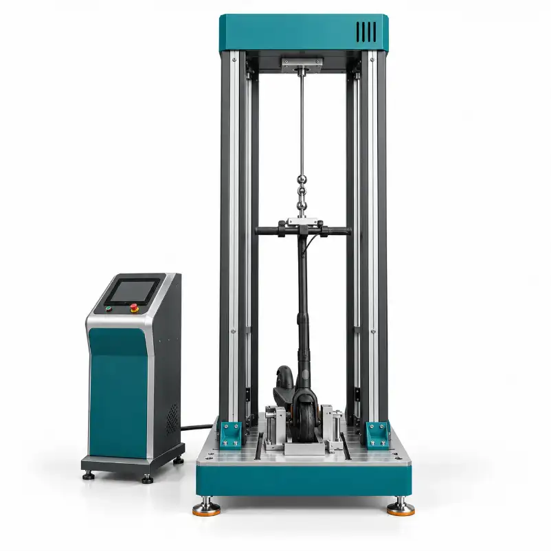
Discuss Derui’s scooter stem fatigue test machine for repeated-load evaluation of a stem or steering column assembly. Define the test boundary and loading programme first, then review the fixtures, drive arrangement, controls and measurement configuration for your project. The objective is a repeatable laboratory test with records your engineering and quality teams can interpret.
Compare structural variants
Evaluate alternative stem sections, joints or assembly settings under the same documented conditions.
Keep comparisons consistent
Use a repeatable mounting and inspection procedure for supplier samples or production checks.
Make the scope clear
Agree on the specimen, working envelope, data and acceptance checks before committing to a configuration.
Specimen Fit: Define What Is Being Tested
Provide a drawing or photographs showing the complete scooter or stem subassembly, handlebar interface, extension height and lower mounting points. Include the intended test position of telescopic sections and any locking or folding joint.
Preserve the intended load path
Identify the force application point and its distance from the restraint. A changed lever arm changes the bending moment. Avoid adding an extra support that bypasses the joint or tube section being evaluated.
Document the restraint conditions
Specify whether the deck, fork, axle or a dedicated specimen interface is restrained. Record clamp positions, tightening settings and alignment so that a later test can reproduce the setup.
For a folding design, distinguish a locked joint subjected to repeated structural loading from a mechanism repeatedly folded and unfolded. These are different test tasks; one fixture should not be assumed to perform both.
Specify the Loading Programme Before Comparing Machines
Share the required load direction, application point, waveform or loading sequence, minimum and maximum force, cycle rate and target count. If the method is displacement-controlled, state the commanded travel and how the resulting load will be checked.
- Direction and linkage: confirm whether the test needs one-direction loading, reversing loading or another arrangement. A tension-only linkage is not evidence of bidirectional push/pull capability.
- Combined operating conditions: review force, travel and cycle rate together. Separate maximum ratings do not demonstrate that all maxima are available simultaneously.
- Control and measurement: distinguish a programmed setting from the measured response. Actuator travel is not automatically the deflection of the stem at the required measurement point.
- Test boundaries: a repeated-load fatigue programme is not automatically an impact, drop, torsion or road-simulation test. State additional tasks separately.
Already have an internal test method?
Send the loading diagram and acceptance criteria, not just a standard number. This gives a clearer basis for reviewing fixture access, load direction, working travel and the records needed from the equipment.
Equipment Configuration and Technical Review
Use the following checklist to define the proposed machine. Request the model-specific specification and agreed operating envelope with the quotation; select numeric ratings against the actual test programme.
| Configuration item | Information to agree | Why it matters |
|---|---|---|
| Specimen and fixture | Complete scooter or subassembly; geometry, extension, restraint points and mounting adjustment. | Prevents an unsuitable fit or an unintended load path. |
| Drive and loading | Actuation method, force direction, control variable, waveform and loading connection. | Matches the mechanism to the specified test rather than an assumed capability. |
| Working envelope | Required force, travel and cycle rate at the same operating condition; target count. | Distinguishes usable test capacity from individual maximum ratings. |
| Measurement | Force and displacement channels, measurement locations, required accuracy and calibration evidence. | Makes readings relevant to the engineering decision. |
| Control and records | Programme settings, completed-cycle count, recording interval, export format and interruption handling. | Supports review of completed and interrupted tests. |
| Stops and safeguards | Travel and load limits, completion stop, specimen-failure criteria, guarding and access controls. | Defines the intended response to abnormal conditions and the safety scope. |
| Installation and delivery | Electrical supply, any air requirement, footprint, access, manuals, training and support responsibilities. | Identifies site needs and what is included in the proposal. |
Test Records That Support a Clear Decision
Agree on the result format before purchase. Useful records connect the specimen and fixture to the loading history, observations and final disposition—not just a counter value.
- Setup: specimen identification, revision, mounting photographs, joint settings, loading point and test method.
- Programme and response: specified conditions, available measured channels, completed cycles and any interruptions or alarms.
- Inspection: the agreed checks for visible cracking, loosening, permanent deformation or a defined change in response.
- Conclusion: whether the acceptance criteria were met, with the inspection evidence and any limitations of the run.
A change in movement may warrant inspection, but it does not by itself identify a hidden crack. Specify an appropriate inspection method if crack detection is required. Stop thresholds and alarm logic also need to be agreed; they should not be described as guaranteed instant detection of every failure.
Agree on equipment acceptance with a representative sample
Review fixture fit and alignment, operation at the intended working conditions, cycle counting, agreed measurement checks, data export and stop logic. Document the checks and acceptance evidence in the technical agreement. An interrupted run should retain its actual status rather than being reported as a completed pass.
A Practical Route from Drawing to Test Setup
Share the specimen
Provide geometry, assembly settings, test method and the failure or acceptance criteria.
Agree on the scope
Review the restraint, load connection, operating envelope, channels and site needs.
Check a sample setup
Use agreed acceptance checks to assess fit, operation, records and stop functions.
Keep the test traceable
Retain the setup, programme, results, inspection findings and interruption history.
Standards: Match the Product, Edition and Test Clause
ASTM F2264 and EN 14619 are relevant names in non-powered scooter testing, but neither should be treated as automatic evidence that this machine meets every requirement or certifies an electric scooter. The official ASTM F2264 scope addresses non-powered scooters; the BSI EN 14619 scope concerns kick scooters.
For a standard-based purchase, provide the required edition and test clause for review. For an electric scooter project, identify the applicable product requirements and market separately. Confirm the fixture, loading method and acceptance evidence against that requirement; performing a single fatigue test does not establish whole-product certification.
Scooter Stem Fatigue Test Machine FAQs
Can the setup evaluate a complete scooter or a stem subassembly?
Either may be a project requirement, but suitability depends on geometry, restraint points and access to the loading connection. Send a dimensioned drawing and assembly photographs so the proposed fixture can be reviewed.
Is stem fatigue testing the same as handlebar fatigue testing?
No. A test focused on the stem or steering column can use different restraints and loading points from a test focused on the handlebar itself. Identify the component boundary and method before choosing the equipment.
Can it test a folding stem?
A folding stem may be evaluated with its joint locked in the specified riding position, subject to fixture compatibility. Repeated folding and unfolding is a separate task and needs its own actuation and cycle definition.
What force, stroke and cycle rate should I request?
Use the values required by your controlled test method. Provide them as a combined operating condition, together with the force direction and loading point. Request confirmation of the model’s usable range, measurement performance and fixture capacity at that condition.
Does a high cycle count prove the stem is safe?
Not by itself. The count must relate to the specified loading conditions, inspections and acceptance criteria. A laboratory result also does not cover every possible service load or establish complete product compliance.
Can the equipment run unattended?
Do not assume this from a programmable counter or automatic stop. Any unattended operation requires a separately reviewed safety arrangement, failure response and site procedure appropriate to the actual equipment and test.
Define Your Scooter Stem Test Project
Send the specimen drawing, assembly photographs, test method, loading diagram, target cycles and inspection criteria. Include required records and installation location so the equipment discussion starts with a clear scope.