Derui chamber


 Message
SCOOTER COMPONENT TESTING · HANDLEBAR & STEM ASSEMBLIES
Evaluate a handlebar design under a defined repeated-loading programme. Derui’s scooter handlebar fatigue testing machine is intended for component projects where the clamp, loading points and assembly condition must represent the part being assessed.
Make the load path part of your equipment specification
Send the handlebar and stem drawings with the test procedure. Review the gripping method, contact adapters and loading sequence before selecting the fixture and controller configuration.
- Match the component: bar width, rise, sweep, clamp diameter and stem interface.
- Define the task: force direction, contact positions, lever arms and cycle sequence.
- Keep useful evidence: setup records, measurements, inspections and reasons for stopping.
Compare Handlebar Designs Without Changing the Test
Evaluate a design revision
Compare tube geometry, material or joining details using the same loading points and mounting procedure.
Assess the specified interfaces
Include the bar, clamp and stem interfaces required by the programme rather than bypassing them with an unrelated grip.
Examine damage or movement
Investigate cracking, permanent deformation or clamp slip with documented inspections and a defined loading history.
Keep specimen preparation, fastener settings and fixture position consistent. A change in clamping can alter the result even when the controller displays the same force.
Define the Clamp, Lever Arms and Loading Heads
Clamp the intended assembly
Identify whether the test concerns the handlebar alone, a bar-and-stem assembly or a larger steering component. Specify the grip location, contact length, allowed surface protection and tightening procedure. For thin-wall or composite parts, review local contact stresses rather than assuming tighter gripping is better.
Locate the applied forces
Record each loading point relative to the clamp and the direction of its force. Bar width, sweep and rise change the geometry. A loading adapter must follow the required contact arrangement without introducing an unintended restraint.
Agree on the relationship between the two heads
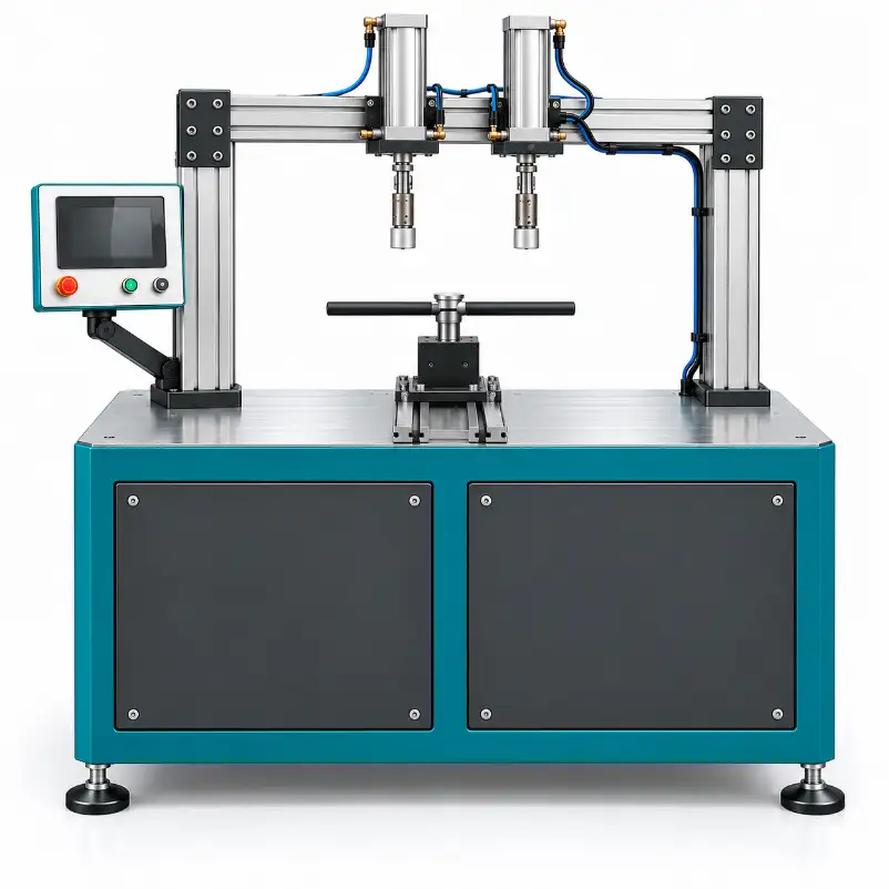
The reference arrangement has two upper loading cylinders. Their presence does not establish independent force control, alternating operation or a defined phase relationship. State the required sequence and ask for a representative demonstration. Steering rotation, torsional loading and vertical bending are different tasks and may need different fixtures.
Force direction and distance from the supported interface affect the loading experienced by the part. Keep a drawing or setup photograph with contact positions and assembly settings.
Handlebar Fatigue Tester Configuration Checklist
Confirm the usable operating range with the proposed fixture and specimen installed. A cylinder size, supply pressure or sensor capacity is not a verified force specification for every setup.
| Item | What your team defines | What the quotation confirms |
|---|---|---|
| Specimen and clamp | Bar profile, width, stem interface and assembly condition. | Fixture drawing, adjustment, contact surfaces and included adapters. |
| Load application | Contact positions, force directions and loading-head relationship. | Rod-end adapters, alignment and achievable loading sequence. |
| Operating programme | Force history, frequency, cycles, dwell and inspection intervals. | Loaded force-motion-frequency envelope and control functions. |
| Measurement and stops | Required force/displacement channels and stopping criteria. | Installed sensors, verification, limits and data retention. |
| Installation and handover | Utilities, access, reporting and training needs. | Services, protection, documentation and acceptance trial. |
Ask the proposal to distinguish supplied functions from options. Environmental exposure, additional specimens, software integration and other loading directions need their own scope review.
A Four-Step Handlebar Test Workflow
Identify the assembly
Record the part revision, preparation, fasteners and procedure. Document its initial condition.
Set the interfaces
Install the grip and loading adapters. Record positions, lever arms and tightening settings.
Run the agreed sequence
Apply the confirmed programme and retain cycle counts, actual channels and interruptions.
Assess the outcome
Examine the agreed areas for damage, deformation or movement using the specified criteria.
This is a planning outline, not a replacement for the operating manual. Inspection intervals and supervision must match the test risks and laboratory procedure.
Ask for Evidence From the Installed Fixture
Use a representative handlebar and the proposed adapters in the equipment acceptance trial. Confirm practical mounting, loading alignment, a defined operating sequence and the agreed stop functions.
- Setup evidence: specimen identity, clamp details, load locations and fixture settings.
- Operating evidence: completed cycles, available measurement channels and interruptions.
- Inspection evidence: damage observations, permanent set or movement, and the assessment method.
- Handover evidence: example records, verification documents, fixture instructions and training scope.
A controller stop does not guarantee detection of every crack. Define both monitored limits and physical inspections. Review guarding around moving heads, specimen failure zones and pneumatic services for the actual installation.
Match the Test to the Vehicle and Procedure
EN 17128 concerns personal light electric vehicles within its scope; EN 14619 concerns non-powered kick scooters within its scope. Provide the relevant edition and exact task for engineering review. A general handlebar-fatigue description does not establish that the same fixture performs every steering, impact or structural test.
Do not transfer bicycle component loads or sequences to a scooter merely because the parts look similar. Use the controlled method to define specimen preparation, loading and acceptance. A component result is not complete-vehicle certification.
For a different loading task, review the scooter stem fatigue configuration or loaded frame fatigue equipment.
Send These Inputs for a Comparable Quotation
- Handlebar and stem drawings, materials, clamp details and specimen variations.
- Loading points, force directions, head sequence and the prescribed operating programme.
- Required measurements, inspection method and acceptance criteria.
- Representative samples, fixture changeover needs and equipment acceptance tasks.
- Available utilities, installation access, protection, training and reporting requirements.
Resolve the fixture before comparing prices
A useful proposal identifies the supplied adapters, achievable operating conditions and required evidence. Share your drawing and procedure so Derui can review the configuration with your team.
Handlebar Fatigue Tester Buying Questions
Can it test different bar widths and shapes?
Compatibility depends on clamp geometry, loading-head adjustment and clearances. Submit each family drawing and confirm the required adapters rather than assuming one universal grip.
Can the two cylinders apply alternating forces?
That must be confirmed for the proposed control and pneumatic configuration. Include the required timing or phase relationship in the technical proposal and acceptance demonstration.
Does it also test steering rotation or stem torsion?
Not automatically. Those tasks use different load paths and may need additional fixtures or drive systems. Define them separately.
Are force curves and export functions included?
Confirm installed sensors, recording intervals and output formats. A touchscreen or cycle counter does not establish continuous force measurement.
Can a completed cycle count predict service life?
It documents the specified laboratory task. A service-life claim requires a justified relationship to field loading and use conditions.
What affects the equipment price?
Fixtures, specimen range, loading programme, control relationship, measurements, protection and acceptance scope determine the comparable configuration.