Derui chamber


 Message
ELECTRIC SCOOTER MOTOR TESTING · DEFINED ENDURANCE DUTY
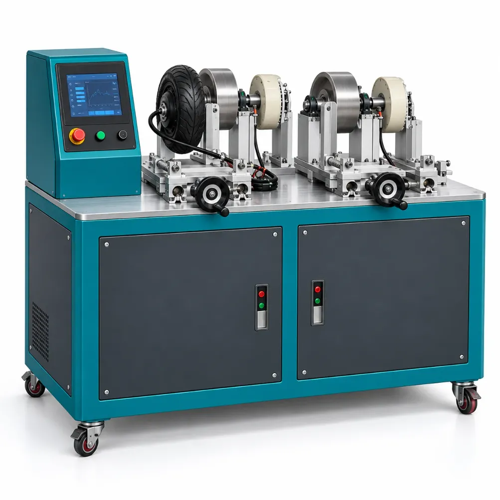
Evaluate motor endurance against a specified operating cycle, not simply elapsed running time. Derui’s electric scooter motor durability test machine is intended for projects that need the motor fixture, electrical supply, loading arrangement and recorded evidence defined as one test system.
Start with the motor, controller and duty cycle
Send the motor drawing and operating requirements with the controller details. Review the mechanical interface, proposed loading method, cooling and measurements before selecting the equipment configuration.
- Define the test boundary: motor only, motor-controller combination or wheel assembly.
- Specify the duty: operating points, transitions, run/rest periods and stopping conditions.
- Confirm the evidence: channels, sensor locations, recording and acceptance demonstration.
Specify the Motor Assembly You Actually Need to Test
A hub motor describes where the motor is installed; BLDC describes its electrical/commutation type. These are not competing categories: a scooter hub motor may be a BLDC motor. Supply the physical drawing and electrical interfaces rather than selecting a fixture from the label alone.
Mount the axle and wheel correctly
Review axle flats, support width, cable exit, wheel/tire envelope and the interface through which load is applied.
Review the coupling arrangement
Define shaft dimensions, mounting pattern, alignment and allowable mechanical loads before choosing a coupling or adapter.
Keep the electrical boundary clear
Identify the controller, supply, wiring, enable/command signals and firmware used during the run.
The reference bench has two worktop stations. The fixture and loading functions available at each station must be confirmed for the quoted configuration; two bays do not prove independent tests or identical capabilities.
No-Load Running and Loaded Endurance Answer Different Questions
No-load operation can reveal some running or assembly concerns, but it does not reproduce the current, heat generation or mechanical loading of a specified loaded duty. If your decision depends on loaded endurance, define how the resisting load is produced, controlled and verified.
Build the cycle around the intended decision
State the required operating points and transitions, run and rest periods, rotation direction, supply condition and cooling arrangement. Define whether the objective is a design comparison, a repeatable production screening task or an engineering durability investigation. Do not equate an accelerated schedule with a proven service-life prediction.
Keep electrical supply and cooling repeatable
A regulated source and a battery pack can behave differently. Record the supply boundary, current limits and controller settings used. Ambient conditions, airflow and temperature-sensor placement also affect thermal comparisons.
Do not assume a bench can reverse energy flow, hold a locked rotor or apply every transient safely. Specify the required operation, protective limits and energy-handling arrangement in the technical proposal.
Choose Measurements That Support the Result
Confirm which quantities are measured, where they are measured and which are calculated. A motor-current value is not a direct torque measurement, and electrical input power is not mechanical output power.
| Evidence required | Measurement boundary to define | Important limitation |
|---|---|---|
| Operating speed | Motor, wheel, drum or shaft location. | Transmission ratios and tire contact can affect interpretation. |
| Electrical input | Controller DC input or motor-side electrical measurement. | These boundaries include different losses and need suitable instruments. |
| Mechanical output | Verified torque/load measurement and corresponding rotational speed. | Fixture drag, coupling losses or contact slip may matter. |
| Thermal response | Defined housing, bearing, winding or other accessible sensor locations. | Housing temperature alone does not establish winding temperature. |
| Endurance history | Run duration, duty steps, interruptions and observed changes. | A timer alone does not document the operating stress. |
If efficiency or a torque-speed map is required, agree on instrumentation, operating points and calculation boundaries separately. An endurance rig is not automatically a calibrated performance dynamometer.
Motor Durability Test Machine Configuration Checklist
| Area | Inputs to provide | Confirm before purchase |
|---|---|---|
| Motor fixture | Assembly drawing, axle/shaft dimensions and wiring clearance. | Adapters, support adjustment, restraints and changeover. |
| Electrical system | Supply and controller details, command interface and operating limits. | Included supply/drive hardware, connection and protective functions. |
| Load and duty | Required operating points, transitions and run/rest schedule. | Loading method, usable torque-speed-power-time envelope and heat dissipation. |
| Station operation | Number of specimens and required independent operation. | Shared services, control limitations and station-specific records. |
| Measurements | Channels, accuracy basis, sampling and output needs. | Installed sensors, verification and an example data file. |
| Installation | Utilities, cooling, access and laboratory safety requirements. | Guarding, emergency stops, electrical protection and handover scope. |
Maximum speed, torque and power ratings cannot automatically be combined into one operating point. Continuous heat dissipation and permitted duty duration must be considered alongside peak capability.
A Four-Step Motor Endurance Workflow
Record the assembly
Identify the motor, controller, firmware, supply and initial condition.
Review the installed setup
Check mounting, connections, cooling, selected channels and the agreed operating limits.
Apply the duty cycle
Retain actual channels, step history, interruptions and stopping events.
Assess the defined outcome
Compare agreed before/after observations and operating changes using the same boundaries.
Execution must follow the supplied operating instructions. Keep the distinction between a controller fault, a fixture interruption and a motor failure in the test record.
Agree on a Representative Acceptance Trial
Use your motor or an agreed equivalent to demonstrate mounting, a defined loaded operating segment, measurement recording and the specified stop functions. Ask for a station-specific sample record rather than accepting a generic controller screenshot.
Confirm any temperature, overcurrent, overspeed and communication-loss protection in writing. Rotating wheels and couplings, electrical energy and possible heat require suitable guarding and laboratory procedures. Appearance concepts do not establish installed protection or permission for unattended running.
This page concerns motor endurance configuration. It does not establish complete-vehicle road endurance, battery fire safety, EMC compliance or certification. For vehicle-level testing, review scooter dynamic durability equipment.
What to Send for a Motor Test Bench Quote
- Motor/wheel or shaft drawing, mounting details and representative samples.
- Controller, supply and signal-interface information.
- Required operating points, load method, duty schedule, cooling and test duration.
- Measurements, output formats, stop conditions and inspection requirements.
- Station count, independence, fixture changeovers and acceptance trial.
- Utilities, installation protection, training and support scope.
Get a configuration matched to your motor duty
Share the assembly details and operating cycle. Derui can review the fixture, loading boundary and required evidence so the proposal separates included functions from optional measurements.
Motor Durability Tester Buying Questions
Can it test BLDC hub motors?
Review the actual motor geometry, controller, wiring and loading interface. BLDC and hub are compatible descriptions, but neither label alone confirms fit or operating capability.
Are both stations independent?
Confirm control, supply, loading and recording for each station. Two visible fixtures do not establish independent duty cycles.
Is a torque sensor included?
That must be stated in the quotation. Current indication, a metallic drum or an adjustable handwheel is not proof of calibrated torque measurement.
Can it measure efficiency?
Efficiency requires appropriate electrical input and mechanical output measurements at clearly defined boundaries. Request those functions and verification separately.
Does motor endurance testing certify the scooter?
No. It evaluates the agreed motor task. Complete-vehicle and electrical safety assessments have additional requirements.
Can it run without supervision?
Do not assume this. Define protective functions, monitoring, fault response and laboratory operating rules for the proposed duty.